Thyristor-based rectifier bridges
The principal references used for the basic understanding of the thyristor rectifier bridges comes from Mohan (2003), Kundur (1994) and Erickson R. (2004), as they all touch the subject, but Erickson R. (2004) goes more into detail. All of them advance the theory of the commutation equivalent resistance due to line voltage notches caused by the line inductance effects. The commutation equivalent resistance has also been used for modeling purposes by Chaijarurnudomrung K.,K. N. A. (2010). The switching process is also thoroughly explained in Kundur (1994), Mohan (2003) and Erickson R. (2004), which gives the basic knowledge needed to make a thyristor rectifier bridge firing board. In Chaijarurnudomrung K. (2010), the rectifier bridge is modeled as an averaged equivalent transformer model by doing the Fourier analysis on the square-shaped line current curves. The result is called the switching function, and can be used to obtain all the steady-state equations of the rectifier bridge given by Mohan (2003), Kundur (1994) and Erickson R. (2004).
The Park Transform
The Park transform is introduced in Kundur (1994) and Krause (2002), but the transform matrices that they use are not the same. For this research, the Park transform matrix used is the one that comes from Krause (2002). Since grids are not always perfectly balanced, properties of the Park transform under unbalanced conditions must be studied. The thesis Dupré (2019) does it, and explains how two sinusoidal signals of same amplitude shifted by 90 degrees can be injected in the inverse transform to obtain a clear harmonics-free negative sequence on the three phase side of the transform. The theory of how the Park transform can be used to transfer differential equations into qd-frame is given in both Kundur (1994) and Krause (2002). Since a phase-angle reference is required for the Park transform, a synchronization device has to be used such as a PLL.
Synchronization devices
The book Best (2003) gives basic understanding of phase-locked loops, and is a good entry-level source on the subject. The author actually explains how and why mathematical models are made for such devices. The performance characteristics needed for a PLL to recover the phase angle properly are given, and the trade-off of the bandwidth versus the response time is explained. Also, the book has a chapter on how to incorporate filters into the loop and stabilize the devices through control problems solving. However, the phase detector used in the book are not what was used in the research simply because the qd-frame phase detector fits better in the body of the research, introducing the need for qd-frame signal analysis.
Two PLL devices are to be designed in the research. One of them uses the usual abc-frame signals and is the Unified Three-Phase Signal Processor (UTSP), first introduced in Karimi (2008), then improved and simplified in Karimi H.,Y. S. (2019). The UTSP is a PLL that is actually able to decouple the sequences of a three-phase signal, and give their angles and amplitudes separately. The other one uses Park transform as a phase detector, meaning that the signals going in the filter are in qd-frame. The article Karimi H. (2012) uses a combination of Clarke and Park transforms as a phase detector since the PLL is to be used for single-phase synchronization. The synchronization device of this research needs to be for three-phase circuits applications, so the Clarke transform was removed. However, the stability analysis method is clearly explained, and thus the filter can be adapted for lower frequency harmonics applications. The line inductance is also assumed to be of high value in the physical applications of the excitation system model, since the excitation transformer is design to attenuate short-circuits, and has high leakage inductance values, therefore notches are always present on the three-phase signals entering the rectifier bridge’s synchronization system.
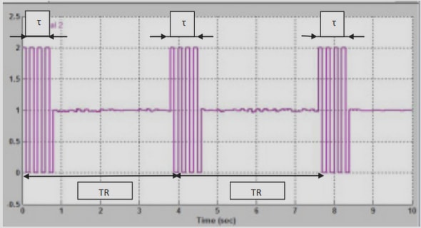
To properly design a synchronization system, the input signals have to be correctly characterized to design the filter accordingly, which must be designed before the loop controller can stabilize the whole thing and set the performance characteristics. The book Corinthios (2009) gives all the knowledge needed for Fourier analysis as well as filter design, with the mathematical background needed to understand exactly how the Fourier analysis can be conducted on the bridge input phase voltages. The article Graham (1993) gives the method for a Fourier analysis done of the input bridge voltage. The Fourier analysis is done on a trapezoidal-shaped line currents (in presence of line voltage notches), then the equivalent impedance seen by the bridge is used to calculate the voltage drop in the equivalent inductance to find the input bridge voltage frequency characterstics. The results given by the Fourier analysis had to be transferred into qd-frame. The only article found on the Park transform’s frequency domain properties Zhang B.,Yi S. (2000), but the results are not proven in any way, and the method’s basic hypothesis are not exactly clearly given. Still, this article gave away the idea that some work could be done on the properties of the Park transform when used on signals containing harmonics.
Modeling of the excitation system
In Krause (2002) and Kundur (1994), the excitation systems are explained, setting the hypothesis used for the excitation system model creation. Those references actually tell us that a transformer is in the excitation loop, as well as a harmonic filter, telling us the exact topology of the excitation circuit used to build the mathematical model. Since the synchronous machine modeling is always in qd-frame, we will use the Park transform to model the whole excitation system. The book Balabanian N. (1969) gives strong techniques for state-space modeling of complex systems called circuit tearing. The technique tells us that the separate subsystems can be modeled and validated separately, before being put together in a functioning global model. Also, the state-space representation modeling method is thoroughly explained in Balabanian N. (1969), as well as the meaning of such mathematical knowledge on a physical system. The state-space model of the excitation system can be used to extract eigenvalues (or closed-loop poles) of the system, much needed for the control system design of the excitation system. It can also be used to conduct transient analysis on the system, which is how the model will be validated.
INTRODUCTION |