Pilot neuromusculoskeletal system
bond graph
State-of-the art
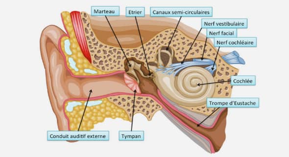
An early review of pilot models is proposed in (McRuer & Jex, 1967); it lead McRuer to extensive work around human dynamics in man-machine systems in (McRuer, Human dynamics in man-machine systems, 1980). Mainly concentrated on aircraft pilot induced oscillations, (McRuer, 1995) distinguishes three main pilot behavioral descriptions which are trajectory following, compensation and precognitive. The compensation behavior could be imagined as the one an aircraft or helicopter pilot would have during an air to air refueling operation. It usually demands fast and short term actions from the pilot. The precognitive behavior concerns anticipative actions based on experience taken by the pilot to make the aircraft reach a desired state. In (Lone & Cooke, 2010), (Lone & Cooke, 2014) review pilot modeling techniques and propose to represent such behavior by discretizing the pilot models into three model categories: sensory models, control models, and biomechanical models see Figure 3-1. The human sensory models represent the dynamics between the inputs of visual cues (through the primary flight display, out of the window cues), the proprioception (cyclic lever see Figure 2, collective lever and pedals positions) and finally the vestibular system (sensing body motion – inner ear) and outputs that are communicated to higher brain functions for processing. Once the brain has processed the information, it sends a decision, also influenced by experience and skills, to the ‘actuation system’ of the human body, its neuromuscular system. This thesis focuses on the pilot interaction with higher frequency helicopters modes also known as aeroelastic RPCs or pilot assisted oscillations (PAOs). A list of incidents is reported in (McRuer, 1995), in which aircrafts such as Lockheed YF-12 or General Dynamics F-111 have been involved in a PAO. Perhaps the most studied phenomena in the open literature concerning aircrafts is the ‘roll ratchet’ phenomena (Hess, 1998), which is “an unwanted and inadvertent high frequency oscillation in the roll axis encountered in high performance fighter aircraft during rapid roll maneuvers” (Höhne, 2000). The same author points out that “it is widely accepted that roll ratchet is influenced by the pilot’s neuromuscular system” and proposes a biomechanical model of the pilot coupled to an aircraft model to investigate the phenomena. It successfully reproduced the incident on General Dynamics F16. This phenomena is also known to have appeared on Eurofighter Typhoon (Lone & Cooke, 2014). In the rotorcraft community, an extensive list of incidents associated to rotorcraft PAOs in the US Navy and Marine Corps is presented by (Walden, 2007). Tiltrotor designs such as the Boeing-Bell V-22 Osprey were very sensitive to PAOs, for which three unstable aeroelastic RPCs in its lateral axis were found after flight testing in (Parham, Popelka, Miller, & Froebel, 1991). The first two modes appeared while on the ground while the last one appeared in the air at high speed. The mechanism behind the first two modes was found to be due to a difference of thrust between the two rotors that was the result of an output of the flight control system due to the involuntary movement of the lateral lever by the pilot. A PAO tendency of conventional helicopters that has been widely studied in the community is the ‘vertical collective bounce phenomena’ for which Sikorsky’s CH-53 Super Stallion was prone when transporting a slung load see Figure 3-2. It is reported in (Walden, 2007) that the load at the end of the cable, a light armored vehicle had once during an incident to be jettisoned In order to better understand the problem and design a solution, (Mayo, 1989) proposed one of the first pilot biodynamics model to be used in industry. This model was obtained by identifications from experiments conducted on one of Sikorsky’s motion-based simulators. The experiment consisted in recording pilot’s collective stick motion while vertical sinusoidal commands were applied to the simulator platform at discrete frequencies ranging from 1 to 5 Hz (see Figure 3-3). It allowed to obtain the transmissibility of different pilots based on their body shapes: mesomorph or ectomorph. This behavior represents an involuntary behavior of the pilots that arises at higher frequencies than those of manual control, in the present example around 3Hz. This behavior is not restricted to aircrafts or rotorcrafts but can appear in any man-machine system and it is usually called biodynamic feedthrough (BDFT). A framework to measure BDFT and its definition proposed by (Venrooij, 2014): “the transfer of accelerations through the human body during the execution of a manual control task, causing involuntary forces being applied to the control device, which may result in involuntary control device deflections”. BDFT therefore explains that when a pilot is engaged in a manual control task under vehicle accelerations, these vibrations can cause involuntary limb motions leading to involuntary control inputs. The experiments presented by (Mayo, 1989) on Figure 3-3 show that BDFT varies between different subjects. Furthermore it is known that pilots adapt their response and therefore their bodies to task instruction, workload and fatigue (Venrooij, 2014). In that same work, BDFT responses of humans were measured when asked to perform different control tasks. The objective of asking one subject to perform different tasks is to force him to adapt his body and therefore his neuromuscular system to the task. The results are presented on Figure 3-4 for the lateral, longitudinal and vertical helicopter axis translations and show that BDFT is also task dependent. These experimental results from (Venrooij, 2014) were obtained on TU Delft’s experimental motion based simulator, for which the subjects were asked to perform three tasks. A position task (PT) with the instruction to minimize the stick position, a force task (FT)
Proposal
However, there has not yet been a consensus on how to model a human arm to compute biodynamic feedthrough as measured in experiments. The model proposed in this chapter is a combination of the models proposed in (Lee & Terzopoulos, 2006), (Pennestri, Stefanelli, Valentini, & Vita, 2007) and (Masarati & Quaranta, 2014). Its originality is twofold, firstly the model is developed using bond graphs and secondly it is applied to the prediction of BDFT on the lateral axis of a conventional helicopter. While computing the left arm of a helicopter pilot movement that controls the collective lever, requires only representing a planar movement of the arm. In the present case of the right arm of the pilot, where he controls the cyclic lever, the arm movement is not planar anymore but spatial and the muscular repartition more asymmetrical; the resulting motion is therefore more complex. In the next sections the computation prediction of biodynamic feedthrough is described and then compared to literature experiments
Upper limb skeleton subsystem and closed kinematic loops
In the upper limb model developed in this work the forearm is considered to be directly attached to the cyclic stick, subtracting the presence of the hand. The arm is attached through the shoulder directly to the airframe, neglecting the motion of any supplementary limb. All the articulations are considered to be spherical joints and represent wrist, elbow and shoulder, see Figure 3-7. Each one of these joints degree of freedom contains stiffness and damping characteristics that are obtained from literature experimental identifications (Mattaboni, Fumagalli, Quaranta, & al., 2009). All the parameters and axes definitions of both arm and cyclic lever are presented on Appendix 4.The human forearm skeleton contains radius and ulna bones but it has been simplified to a single rigid body representing the characteristics of both bones. The humerus is also considered as a rigid body leading to a skeletal model of 2 rigid bodies and 9 degrees of freedom. The multibody model is developed using the approach presented in the previous chapter. When this skeleton subsystem is not attached to the cyclic stick it can be seen as a chain of bodies see Figure 3-8. However, once it is attached to the cyclic stick, both cyclic stick and arm are attached to the rotorcraft airframe leading to a multibody system that contains a closed kinematic chain (CKC) or loop on Figure 3-8. The computation of numerical solutions of multibody systems with a (CKC) is challenging because the topological loop (Figure 3-8) leads to equations of motion in the form of DAEs of a higher index14 than 2, usually 3, see (Dabney, 2002) .