Bulk Metal Forming Process
Metal forming process consists of series of deformation steps in which a metal billet or blank, received after casting is shaped by tools or dies. The pattern and mastery of such processes depend on an understanding of the features of the workpiece material, the conditions at the tool/workpiece interface, the mechanics of plastic deformation (metal flow), the equipment used, and the finished-product requirements (Hurtuk). These elements determine the choice of tool geometry and material as well as processing conditions (e.g., workpiece and die temperatures and lubrication). Due to the complexity of many metalworking operations, analytical, physical, or numerical models are often relied upon to design such processes. Metal-forming processes are usually classified according to two broad categories:
• Bulk, or massive, forming operations
• Sheet forming operations
In both of these processes, the surfaces of the deforming metal and the tools are in contact. The friction between the metal and the tool have a major influence on material flow during deformation. In bulk forming process, the input material is in billet, rod, or slab form, and the surface to volume ratio in the formed part increases considerably under the action of high compressive loading. Whereas, in the sheet forming process, a piece of sheet metal is plastically deformed by tensile loads into a 3D shape, often without significant changes in sheet thickness (Dieter, Kuhn et Semiatin, 2003).
Forging
It is a bulk deformation process in which the shape of a material is changed by squeezing i.e. with a mechanical or hydraulic press or by hammering . The deformation breaks down the cast microstructure and the resultant directional alignment of the fiber make the forged ingot stronger and more ductile than casting process which results in greater resistance to shock and fatigue (Dieter, Kuhn et Semiatin, 2003). Forging is basically of two types, Closed Die forging and Open Die Forging.
Closed Die
The forging partially closes the workpiece material and thus restricts the flow of the metal. The hot metal is enclosed in the dies of a predefined shape . The force is applied to the dies to give the impression to the hot metal .
Open Die
The hot metal is squeezed or hammered between flat, V-shaped or circular dies. The metal flow is not completely restricted due to the fact that the work piece is not enclosed ,Open die forging is usually used when the size of the forging is too large to be produced in a closed die.
Ingot Breakdown Process
In order to break down the initial cast microstructure which is composed of the chill zone, columnar zone, and equiaxed zone, to wrought structure, open die forging is used to deform the large ingot into a short wide ingot by the action of repetitive die blows. This process is known as ingot breakdown process (Dieter, Kuhn et Semiatin, 2003). This process not only converts large, non-uniform grains (cast microstructure) to wrought microstructure but also is useful for reducing chemical heterogeneities present due to segregation of various elements due to diffusion process of alloying elements. In the case of steels, the ingot breakdown process is usually conducted in the austenite phase . The operation consists in heating the ingot and held for ~24hrs in a furnace to about 1260 °C. It is then transferred to the forging press where through a multi-hit process incremental deformation is applied to the ingot. Due to this, various microstructural changes occur, like dynamic softening such as dynamic recovery (DRV), dynamic recrystallization (DRX), dynamic transformation (DT) and metadynamic recrystallization, MDRX. To attain the final shape of the ingot, deformation is done along the various axis of the ingot.
Iron Carbon Phase Diagram
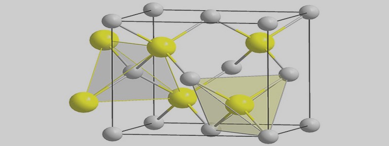
Upon heating pure iron to 910 °C, the crystal structure transforms from body-centered cubic (BCC) to the face-centered cubic (FCC) structure known as austenite or γ iron. This structure or phase of iron is fully austenitic up to 1390 °C. Above 1394°C, the FCC structure of iron transforms back into the BCC structure, known as δ iron, which remains ferritic until it melts at 1538 °C. The austenitizing temperature lowers down to 723 °C upon the addition of carbon as an alloying element when it nears the eutectoid point with 0.8 wt.% carbon content.
Some important boundaries at single-phase fields have been given special names. These include:
• A1: Eutectoid temperature, which is the minimum temperature for austenite.
• A3: The lower-temperature boundary of the austenite region at low carbon contents; i.e., the gamma/gamma + ferrite boundary.
• Acm: The counterpart boundary for high-carbon contents; i.e., the gamma / gamma + Fe3C boundary (Bhadeshia, 2002).
Sometimes the letters c, e, or r are included e.g. Ae1 or Ae3.
The boundary between the initial formation of ferrite and pure austenite is known as the Ae3 temperature, which is a very important temperature in the present study. As the temperature slowly decreases, all the austenite transforms into a ferrite + pearlite microstructure at the Ae1 temperature or 723 °C. Pearlite microstructure consists of a lamellar structure of ferrite and cementite (Fe3C). The maximum solubility of carbon in the ferrite and austenite phase is 0.02 wt.% and 2.14 wt.% respectively. This solubility limit depends on the crystal structure and the conditions of the interstitial sites available for the carbon atoms to fill.
The addition of other alloying elements significantly changes the Fe-C phase diagram, especially with regard to the constancy of the ferrite and austenite phases. The concentration of these alloying elements results in the shifting of phase boundaries. Alloying elements such as C, Co, Cu, Mn, N, and Ni are known as the austenite stabilizers. They lower the eutectoid temperature and widen the range of temperature over which the austenite phase is stable. In contrast, alloying elements such as Al, Cr, Mo, Si, and W are known as ferrite formers, increase the eutectoid temperature thereby restricting the formation of the austenite phase. The addition of alloying elements also improves material properties such as the corrosion resistance (Aranas Jr et Jonas, 2015).
INTRODUCTION |
![]() Télécharger le document complet
Télécharger le document complet