Aero-derivative gas turbine engine
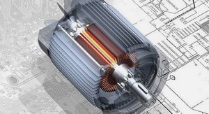
The ADGTEs were created from aero-gas turbine engines, which give them lighter weight, faster response and a smaller footprint compared with their heavy duty GTE counterparts. They can operate on a very wide range of fuels (natural gas and liquid fuel) with low NOx emissions (below 25 ppm) using DLE combustors or water injection (Gülen, 2019). They are usually offered as packaged units with prefabricated accessory modules for rapid installation. Their modular design also enhances their operability and maintainability. ADGTEs are often seen as a good choice in smaller-scale (up to 200 MW) energy generation.
The conversion from aero GTE to ADGTE is accomplished simply in a single shaft GTEs by replacing the nozzle with a free turbine, for example the Rolls-Royce Avon (Fletcher, 1963). In two shaft turbofan GTEs, the conversion operation includes removal of the fan, modification of the LPC to overtake the duty of the removed fan, modify the LPT to drive the modified LPC , for example the LM 5000 ADGTE based on the CF6-50 turbofan GTE (Haaser & Casper, 1991). However, the conversion of a big three shaft turbofan GTE has followed another approach. In this approach, the intermediate pressure and high pressure cores are retained, the LPC is redesigned (essentially taking the place of fan root and the original LPC), and a new LPT is redesigned to act as a drive for the new LPC and the load (Horlock, 1997). The three shaft Siemens SGT-A65 ADGTE which was derived from Rolls Royce RB211 Trent 60 represents an example to this approach.
The gas generator of ADGTE generates a high-energy gas stream that can be used to provide shaft power which is determined by fuel flow and the management of airflow through the compressor stages. The engine control system must ensure that the desired power output is achieved. However, the engine control system must also protect the engine from exceeding any design limits under both dynamic and steady state conditions throughout the operational envelop. These limits include component speeds, temperatures and operating regions which can result in compressor surge. The control strategy normally involves a set point and the control system drives the engine towards the set point. There are two types of controls in ADGTE (Gülen, 2019):
• Speed control (governor).
• Temperature control.
A speed control system can operate in either the isochronous mode or the droop mode. In general, droop mode is applicable to operations when the engine is connected to a grid. On the other hand, isochronous mode is applicable when the engine is not connected to the grid and operates in an isolated or islanded mode (Nguyen, 2000). In the isochronous mode, the control system maintains a constant reference speed regardless of load. When a load change occurs, there is a momentary change in speed during the transient . On the other hand, in the droop mode the reference speed varies with load. Again, during transient conditions, there will be momentary speed change, but after the transient the speed will settle at a new reference speed value determined by the droop % of the generator.
Siemens SGT-A65 ADGTE – Overview
Engine configuration
The Siemens SGT-A65 is one of the world’s leading ADGTE used in the power generation and oil-and-gas compression industries. It is the industrial version of the Rolls-Royce Trent 60 high by-pass-ratio aero GTE, which has high efficiency, and in service on the Airbus A330 and Boeing 777. The SGT-A65 is capable of producing 65 MW at thermal efficiency of 42% (H.I.H. Saravanamuttoo, 2017).
Siemens SGT-A65 DLE three spool ADGTE is used as a case study in this dissertation . It has a two-stage low pressure, eight-stage intermediate pressure and six-stage high pressure compressor, with DLE combustion. Furthermore, both high pressure and low pressure turbines consist of a single stage each, and the power turbine has five stages used to drive the low pressure compressor and the power generator at fixed speed (3600 rpm used for power generation at 60 Hz).
Engine control system
The SGT-A65 ADGTE control system schedules the fuel flow to maintain the engine power or speed at a predetermined speed (3600 rpm). As the electrical load demand on the LPT increases, additional torque is applied on the LPT shaft decreasing its speed. The control system responds to the change in speed by increasing the fuel flow to the combustion chamber, to bring the speed back to the preset value. As the load demand decreases, lowering the torque applied on the LPT, allowing the speed to increase. The control system responds by decreasing the fuel to the combustion chamber, to bring the speed back to the preset value.
The control laws of the engine control system are the algorithms or control logic which govern the operation of the engine. This logic is embedded within software installed in a microprocessor based electronic controller. The software handles the processing of all inputs from the various sensors (thermocouples, pressure transducers and speed inputs) laid out across the engine. The software calculates the scheduling of the various gas metering valves, pressure regulating valves, vent valves, air valves, and variable geometry and controls them by outputting signals to multiple actuators via torque motors and solenoids.
The ECS of SGT-A65 engine in a power generation application carries out three primary functions: Start/stop sequencing, Control, and Protection. Start/Stop sequencing function controls the engine start and stop operation by providing the proper signal required for normal and safe operation. In addition, it is pushing the engine to shut down under all possible abnormal conditions like equipment or control system failure. The start sequence proceeds through five different states before the engine achieves the synch-idle condition: Dry cranking, Purging, Light up, Sub synchronous idle, and Synch idle. Synch idle is defined as the condition where the LP spool speed matches the frequency of the grid with which it will have to be synchronised (3600 rpm for 60 Hz, 3000 rpm for 50 Hz) while in a no load condition.
The control function of the ECS is different depending on whether it is in grid mode operation (Droop mode) or in isochronous mode operation. In the isochronous mode the control system controls LP spool speed rather than power. As the load increases, the LP spool will droop from its reference until the engine can produce enough power to match the load and return the LP spool back to its synchronous (steady state) speed. Conversely, if load is removed, the LP spool speed will overshoot its reference and engine power will have to reduce to return the LP spool back to its synchronous (steady state) speed. In the droop mode the steady-state speed varies with load .
INTRODUCTION |
